Lets continue with another in our “Behind the Circus” series: Engineering Drawings
Most people that have seen or played Pinball Circus remember the crazy amount of wireforms and playfields that the machine has.
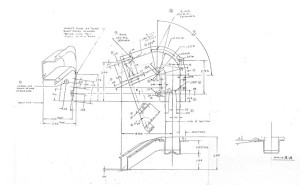
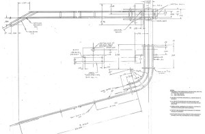
Every one of those wireforms, ramps, playfields, and custom mechs have an associated engineering diagram.
While we had many of the original drawings, most either needed to be digitized for CNC use or sometimes recreated. Luckily we have a great engineer on our team that made this much less painful than it could have been.
We had nearly all of the original ramp and wireform engineering drawings, but even those were a slight challenge as there were sometimes many revisions to the drawings so we had to make sure that we used the final version.
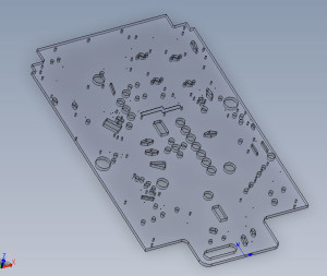
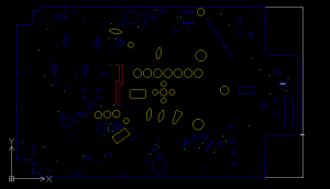
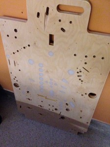
Some drawings, such as the playfields themselves, had to be digitized and slightly modified based on the changes/enhancements that Python requested. All of the playfields were first done in Solidworks, and then we created a separate file based on those solidworks files to be used for the CNC paths. Can you spot any of the new changes on the main playfield?
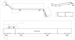
The set of engineering documents that needed the most manual intervention were the ball guides. But again, our solidworks expert made quick work of them. From these drawings the ball guides could then be laser cut and bent into their appropriate shapes.
Hopefully everyone is enjoying these behind the scenes posts. I think the next post we will change it up slightly and talk about some of the interesting trips we took while working on this project with Python.
Until next time.
Can’t wait to buy this.